Sunday, July 29, 2012

Big Reveal

I think we have had enough background now.  Let's move on to see what our efforts have brought!

Mixing It Up

The basic idea is to use two video modes to display somewhat different versions of the same original image.  By alternating between these two images, we should produce an image that our eyes will blend into something that better represents the original than either does by itself.

The first implementation of this idea involved simply taking the output from my earlier efforts and modifying the code a bit to implement the continuous mode switching.  The modifications were simple: relocate the data so that both screens could be resident in memory at once; and, chain the code sections together so that each mode would be displayed in turn for 1/60th of a second for each mode.  In this implementation, none of the image data generation was changed at all -- both modes were still independent attempts to reproduce the original image.

Mode Swapping w/ Independent Images


The combination of the two "best effort" images does yield an improved result.  But what we really want is to use the second image to compensate for quantization error in the first image.  As it stands, the combined color for any given pixel is often limited to being only as good as the best match for that pixel in either of the two "best effort" images.  Only if the original pixel's color was between the colors in the "best effort" images will the combined image's pixel actually be an improvement.  Conversely, in most cases the resulting color for that pixel will be worse than that of the same pixel in the better of the "best effort" images!

To improve this, I decided to make one of the mode's generated image data depend on the image data generated for the other mode.  The first mode's image is still generated in a "best effort" fashion.  Once that image is generated, the color error for each pixel is calculated, doubled, and applied to the input for the generation of the second image.  This distorts the second image in a way that brings the combined image closer to the original than either "best effort" image would be likely to achieve.

Given the above, one must wonder which mode's image is generated first?  The "semi-graphics" mode is both lower resolution and less flexible with its color placement.  To me, it seems like a good bet to let that remain in the role of "best effort" image.  The "color graphics" mode's higher resolution and it's somewhat greater flexibility in placing colors should make it more effective at matching the distorted second image.  The above is conjecture, so YMMV -- I am pleased with the results I have gotten so far.

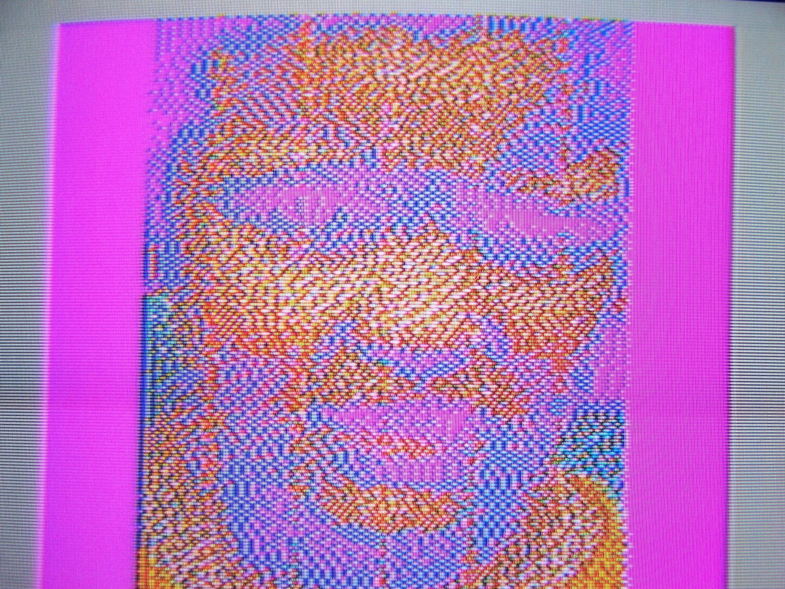
Mode Swapping w/ Error Redistribution

Fighting Flicker

Flicker is going to be an inevitable by-product of this technique.  Nevertheless, it is a distraction.  Even if we can't avoid it, we should attempt to minimize it.

AFAICT, flicker is more prominent when the luminance (aka "brightness") of the color on one screen differs significantly from the luminance of the color in the same position on the other screen.  Obviously, large areas of such combinations produce more noticeable flicker as well.

As I mentioned previously, I am already using the YIQ color space for matching colors.  The 'Y' part corresponds to luminance, and it is the biggest factor for matching colors in that space.  Hopefully this is already helping to reduce luminance differences between the two screens.  In any case, I don't have any other ideas to address this part of the problem...

It is notable that the VDG uses different border colors for "semi-graphics" (black border) and "color graphics" (black or buff, depending on CSS value) modes.  By default, switching between these modes produces a large flickery mess around the border of the screen.  Fortunately, clever timing allows for reconfiguring the VDG so that a single mode is always selected while the border is being drawn.  The images above use this technique to minimize flicker on the screen.

Winding Down

The end of July is approaching, and with it will come the end of the Retrochallenge event.  I'm fairly happy with where things stand, so I probably won't be adding much more to this project between now and then.  I probably will try to clean-up some code, push-out a git tree, and maybe write a little "wrap-up" post...stay tuned!

Friday, July 27, 2012

Palette Redux

In the previous couple of posts, we have discussed how to drive the CoCo's VDG to display 8 on-screen colors even when using the VDG's 4-color graphics mode.  This has yielded a substantial improvement in the quality of "real life" images converted for display on the CoCo, but the results are still lackluster.  In particular, the lack of black is a glaring problem in the display of many images.  I think we can do better.

Ingredients

So, lets review our best performing options....

The "color graphics" mode with the dynamic CSS configuration gives us 8 colors on the screen at once.  The palette remains a bit limited, and any given segment of 16 pixels must share the same 4-color palette.  But, dithering and the ability to select different palette combinations for each row on the screen combine to enable generating images on the CoCo that well represent their source images.  The biggest drawback of this mode is the lack of black in the display.

The "semi-graphics" mode provides for 8 colors on the screen and includes the ability to add black into the mix as well.  But, this mode is restricted to half the horizontal resolution of the "color graphics" mode.  Further, any given pair of these lower-resolution pixels is restricted to either sharing the same color or to using one color and black between the two of them.  Obviously, these limitations produce more "blocky" results than one gets with the "color graphics" mode.

So, we have two mediocre options.  It would be nice if we could find a way to combine the advantages of each of these modes...

Flip Flop

It seems like the biggest problem with the CoCo's graphics is the lack of available colors.  One tricky technique that can be used to increase available colors is to draw different colors on alternating screens.  When those screens are alternated quickly enough (e.g. every 1/60th of a second), the eye tends to blend those colors, forming a new set of colors.  Perhaps we could alternate between the "semi-graphics" mode and the 8-color "color graphics" mode, producing a larger suite of combined colors?  The lack of black in the "color graphics" mode will still prevent us from having a true black for our converted images, but hopefully a gray or even a darker blue will at least be a more suitable replacement for black than the bright blue we have now.

We are already changing the VDG configuration mid-screen and even mid-line.  It is, of course, also possible to change the VDG configuration between screens.  In fact, this basic technique has often been used to facilitate "page flip" animations.  So, let's use this technique to produce a new combined graphics mode.

Proof Of Concept

I started with the earlier palette test application.  To that, I added initialization of a "semi-graphics" screen buffer with a series of horizontal lines in all 8 colors plus a 9th area on the bottom right of the screen that is all black.  Then, I changed the code so that after displaying the "color graphics" screen it would then reinitialize the VDG for "semi-graphics" mode.  After that screen finishes, the VDG is reinitialized for the "color graphics" mode again and the whole process is repeated.  The result is a display of all the available colors in the combined mode.

Mode-Flipping Palette of 44 colors!

If my math is correct, that should give us 44 colors to use -- I counted just to be sure!  That should lead to quite an improvement in our image conversions.  On the downside, there is some noticeable "flicker" on the screen when using this technique.  There may be ways to minimize that effect, but it is probably not completely avoidable.  Hopefully the bounty of new colors will more than compensate!

Stay tuned to hear about how I'm using this combined mode for image conversions...

Thursday, July 26, 2012

Pick A Color

Putting more colors on the screen is great, but it should be clear to the reader that there are certain rules that must be followed in order to make it possible to use those extra colors.  If we were to draw a cartoon image, then we could allocate the colors ourselves while applying the rules manually.  That seems likely to have been the process used by the Dragonfire creators.  But what about converting a real-life image (i.e. a digital photograph) for display on the CoCo in eight on-screen colors?

Palette Definition

Anyone that has ever matched paint colors knows that color matching can be a tedious and subjective process.  Performing that task for the 24,576 pixels on the CoCo screen will require some automation.  The first step towards automating that selection is to obtain a mathematical definition for each available color, thereby transforming the subjective process of color matching into an objective process instead.

In lieu of better information, it would be tempting simply to "guess"-timate the RGB values for the colors generated by the VDG.  One might presume that each color is relatively close to an easily defined position in the RGB color space, and such a definition might even be close enough to achieve reasonable mappings.  Fortunately, such a slipshod process is unnecessary -- some MESS folks figured-out a more refined palette definition based on mathematics and the VDG's datasheet.

Matching Colors

The math required to compare two colors might not be obvious to everyone -- it wasn't originally obvious to me.  After all, is "red" closer to "purple"?  Or "orange"??

The RGB mapping of each color can be treated as a 3-dimensional coordinate in the RGB "color space".  Once you wrap your head around that, the solution becomes more clear -- colors located nearest to one another in a color space are the colors that match each other best.  The Euclidean distance between the RGB values for each color is used to determine which of the colors in the CoCo's palette is the best match for a color in the image being converted.

Now, get this -- there is more than one color space available to model color.  This seems like an odd curiousity until one realizes that each color space emphasizes different aspects of color.  This means that for any given pair of colors, the relative distances between those colors will differ depending on which color space is used to model them.  I find that the emphasis on luminance in the YIQ color space gives it the best color matching results on the CoCo, so I convert my RGB color values to YIQ values before doing color matching comparisons.

I mentioned dithering in an earlier post.  Dithering can be messy and distracting, and for old folks it looks a bit like fuzzy analog television reception.  But, it can be very effective at improving color perception for a given image.  So, I tend to dither my images while converting them for the CoCo.

Making Choices

The discussion above is just as applicable to a statically configured VDG mode as it is to the 8-color mode we have been describing.  But the 8-color mode has one more wrinkle -- the palette must be set correctly for each block of pixels.  I don't know of any clever way to predict which palette option is going to be the best for a given set of pixels.  So, I simply do two sets of color matches for each group of pixels!

Since I can do 8 palette change for each line, I divide each line into 8 groups of 16 pixels each.  I then do the color matches and calculate the accumulated color error for each set.  After that, I choose the palette that produces the least total color error for each set of pixels.  Finally, I record which palette I choose for each set and store the corresponding image data to the output.  I later emit assembly code to perform the palette switching at the appropriate times for each line of the display.  In effect, I compile the image into a binary program for the CoCo.

Test Image In 8 On-Screen Colors

Initially I was concerned that the 16-pixel groups on each line would result in obvious blocks of colors from each palette on different parts of the screen.  But, I think that the ability to choose different palette combinations on each line combines with the dithering to mitigate any tendency to group colors on the screen.


Well, things are looking a bit better.  But I think that we can still improve upon these results -- eight colors is still a bit paltry.  Next time we will look at a way to combine a couple of CoCo video modes to extend the CoCo palette even further.

Wednesday, July 25, 2012

Palette Expansion

The graphics output options for the original CoCo are a bit sad when using a static VDG configuration.  We are forced either to give-up half of our available colors (and black) to maximize resolution, or we must give-up half of our available resolution and accept some odd color placement rules to maximize our available colors.  Neither option provides particularly satisfactory results.

CoCo Chameleon

The VDG uses the inputs on a number of pins to determine its current video mode.  On the CoCo, this is used to switch between alphanumeric and semi-graphjcs modes automatically.  The highest-order bit of each byte of screen data is fed back into the pin that selects between those modes, allowing each character to be displayed as intended.  The selection between inverted and non-inverted characters is handled similarly.

In fact, there are other VDG-equipped machines that extend this same technique to control the pin that selects between the available palettes (i.e. the CSS pin).  But for better or for worse, the CoCo has to use software to control the CSS value.  So that begs the question of whether or not the CoCo can change the CSS value quickly enough to produce more colorful displays.  In fact, the CoCo game Dragonfire does exactly this.  While the Dragonfire display is a bit cartoon-ish, it suggests that more colorful displays are possible on the CoCo.

Timing Is Everything

Knowing that we can switch the active palettes "on the fly", we are now faced with the task of doing so in time to display what we want when we want it.  To do that, we have to figure-out how often we can change the CSS value, and when to do so.

Let's start with the 'when' part...  The CoCo hardware can generate an interrupt for each line of the (almost-)NTSC display, or 262 times for every frame.  Processing these interrupts through the IRQ vector would take a lot of cycles -- enough to miss the beginning of the actively displayed portion of the next line!  Fortunately, the 6809 provides a SYNC instruction that basically halts the processor until the next interrupt is signalled.  This allows us to synchronize with the interrupt timing at a minimal cost of CPU time.  A little extra processing lets us skip the 70 lines during the vertical blanking period (i.e. the non-active portion of the display at the top and bottom of the screen).  After that, some judicious use of NOP instructions and cycle counting allows us to time our CSS updates as necessary.

Each VDG clock cycle corresponds to one "color clock" cycle on the NTSC display, or one color pixel on the screen.  The CoCo CPU clock is the VDG clock divided by 4, so one CPU clock corresponds to 4 color pixels on the screen.  The fastest way I have found to update the CSS value is to preset the A and B registers and then use STA or STB to store the appropriate CSS value to the register that controls the VDG mode (including the CSS input of the VDG).  With the 6809's Direct Page register set appropriately, those STA/STB instructions each take 4 CPU cycles.  That corresponds to 16 color pixels on the screen during each CSS update, allowing for 8 CSS updates per 128-pixel line.  Presetting the CSS value could allow for up to 9 CSS values (the preset CSS value and 8 updates) per line, with each CSS value corresponding to a different palette selection.

Putting Things Together

With all that figured-out, it seems prudent to write something to prove that this all works!  So, I wrote some boilerplate code to properly time the CSS updates and to divide each line into eight 16-pixel sections.  I added some code that initialized the screen buffer to include the appropriate pixel data for a rainbow of colors, accounting for the changing palettes in each section.

8 On-Screen Colors from VDG

Keep in mind that for any given byte of screen data, only four colors are available.  Yet, there are eight colors displayed on each line.  Now we are getting somewhere!  Stay tuned to hear about how I use this to improve the display of a real-life image... :-)

Sunday, July 22, 2012

Level Setting

This project is about getting better-than-expected graphics output from the TRS-80 Color Computer (aka "CoCo").  With that in mind, it seems reasonable to review just what sort of graphics output one would normally expect from the CoCo.

Most graphics on the CoCo are produced using static graphics configurations -- the VDG registers are setup at the beginning of a program and changed only rarely while the program runs, if at all.  There are only a handful of available resolutions, and only a few color options.  Further, each color option brings its own set of restrictions and compromises.  I described the available statically configured graphics modes in an entry on the Fahrfall blog.  Those so interested might wish to review that information.

Original image used to generate examples below.


Color Commentary

The "color" graphics modes of the CoCo's VDG are only able to display 4 colors at a time.  Worse, the palette of colors must be chosen between two pre-defined groups: green, yellow, blue, and red; or buff (almost white), cyan, magenta, and orange.  Note that black is not an option in these modes.

Green, Yellow, Blue, and Red

Buff, Cyan, Magenta, and Orange


For the most part, these modes are a bit awful.  They are reasonably serviceable for a variety of game activities, but they don't make for good display of "real life" pictures.

Dithered Green, Yellow, Blue, and Red

Dithered Buff, Cyan, Magenta, and Orange


Dithering improves (or at least changes) the output a bit.  But for the most part, the resulting images are still horrible.

Block Party

The VDG's semi-graphics modes can use all eight of the aforementioned colors on-screen at once, even in a static configuration. Black is available as well.  On the downside, the semi-graphics resolution is only 64 pixels wide!  Also, for every pair of pixels either both must be the same color or one of the pair must be black.

Semi-Graphics (8 colors + black)

Dithered Semi-Graphics


Access to the full(!) range of colors improves the color fidelity of most images.  But the reduction in resolution isn't necessarily worth the trade-off.

Left Overs

I'm not going to cover the NTSC "artifact color" mode at this point.  It is more painful to use, since its color numbering changes somewhat randomly according to how the CoCo comes out of reset.  In any case, it is really just another 4 color mode.  Suffice it to say that it is comparable to the "color" graphics modes in terms of image fidelity.

Anyway, I hope that the above provides some good background on what CoCo graphics displays tend to be like.  There is plenty of room for improvement!  Luckily, dynamic VDG configuration changes greatly expand the possibilities for better CoCo graphics...

Saturday, July 21, 2012

Better Graphics for the TRS-80 Color Computer

I am a fan of the TRS-80 Color Computer.  That was the first computer which I had as a kid, and it has continued to entertain me as the main object of my retro-computing hobby for about three decades.  Perhaps interestingly, one of the ironic things about the TRS-80 Color Computer (aka "CoCo") is that even in its own time the CoCo was never really regarded as a great graphics performer.

The original CoCo relies on the Motorola 6847 Video Graphics Controller (aka "VDG").  On paper, the specifications of the VDG compare reasonably well to those of its contemporaries.  But, it is restricted to the use of one of two 4-color palettes in its graphics modes -- both sets being rather hard on the eyes and neither containing black.  It does offer a set of "semi-graphics" modes that allow for the use of all 8 colors plus black, but that comes at the price of even lower resolution.

The CoCo3 is different, of course.  But even with the advent of Fahrfall, in my opinion the original CoCo (and CoCo2) remains a bit under-loved.  Besides, the project I have undertaken will teach me some crucial details about timing on the CoCo.  Hopefully those details will help me add some final features (like in-game music) to Fahrfall!

Raster Effects

The CoCo wasn't the only machine to use the VDG.  Another machine using the VDG was the Dick Smith VZ200.  At some point I was surfing the web and came upon an article about the VZ200 that describes changing VDG display modes while the screen is actively being drawn, allowing for more than one mode to display on the screen at a given time.  Looking closer at the datasheet for the VDG also reveals that the mode control inputs "may be changed on a character by character basis".  In fact, this is exactly the technique the CoCo hardware uses to choose between displaying alphanumeric characters and semi-graphics blocks.

The ability to change modes "on the fly" provides some flexibility not otherwise available to a static VDG configuration.  In exchange for some properly utilized CPU cycles, we can create a variety of custom video modes.  This capability can be used to enable the use of all 8 colors (but still no black) in the VDG's color graphics modes.

Flicker Mode

Another technique that others have used to improve available color counts is to alternate between two screens of graphic data for a given image.  By doing this switching quickly enough (one switch every 1/60th of a second), the two screens blend to create a new image in the viewer's mind.  I recently came across a presentation describing just this sort of technique being used to produce 105-color images with the 15-color palette available on the MSX1.  A particular point about that presentation gave me an idea about how to combine a couple of VDG modes to produce improved graphics output on the CoCo.


So, hopefully that provides an outline of my entry for this Summer's Retrochallenge event.  Much of the work is already done, but it still needs a good write-up -- I intend to provide that over the next week or so.  In the meantime, I hope that everyone will enjoy my little CoCo project!